
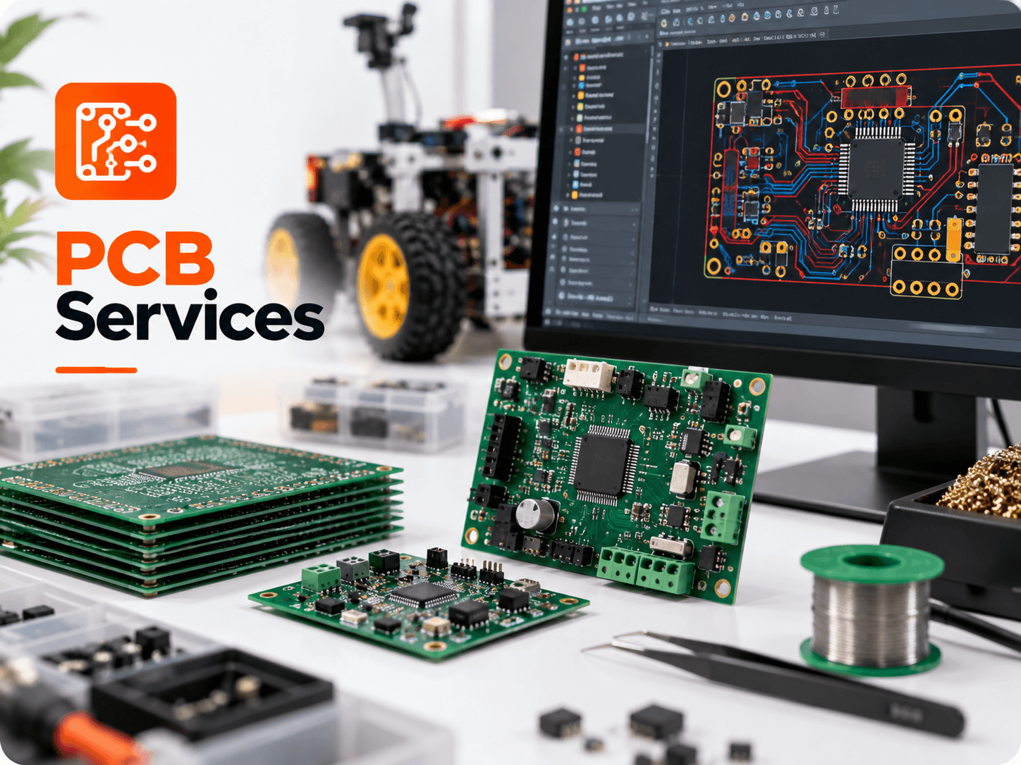
In the electronics manufacturing industry, Gerber files are the universal language between design engineers and automated fabrication machinery. Just as 3D printers interpret G-code or CNC mills read DXF paths, photoplotters and etching machines read Gerber vector data to image conductive copper traces, solder masks, and silkscreen text. If you are preparing to order circuit boards, here is an explanation of the files your manufacturer expects inside your ZIP archive.
What Is the RS-274X Gerber Standard?
The RS-274X format (Extended Gerber) is an open ASCII vector format that defines 2D binary images. Each layer of your circuit board is exported as a separate file containing coordinate commands and embedded aperture definitions (flashes, lines, polygons). This eliminates the need for separate aperture wheel lists required by obsolete legacy standards.
Standard Layer File Extensions Decoded
| File Extension (Protel/Altium) | KiCad Naming | Layer Description |
|---|---|---|
| .GTL | *-F_Cu.gbr | Top Copper Layer (traces, pads, copper pours) |
| .GBL | *-B_Cu.gbr | Bottom Copper Layer |
| .G1 / .G2 | *-In1_Cu.gbr / *-In2_Cu.gbr | Internal Ground / Power Planes (for 4-layer boards) |
| .GTS | *-F_Mask.gbr | Top Solder Mask (openings where copper will be soldered) |
| .GBS | *-B_Mask.gbr | Bottom Solder Mask |
| .GTO | *-F_SilkS.gbr | Top Silkscreen (component designators, logos, pin 1 marks) |
| .GBO | *-B_SilkS.gbr | Bottom Silkscreen |
| .GKO / .GM1 | *-Edge_Cuts.gbr | Board Outline / Mechanical Keep-Out (milling boundary) |
| .DRL / .TXT | *-PTH.drl / *-NPTH.drl | Excellon NC Drill Files (via and component hole coordinates) |
| .CPL / .XY | *-pos.csv | Pick and Place Centroid File (for automated SMT PCBA) |
Why Drill Files and Centroid Files Are Separate
A common misunderstanding is that Gerber files contain hole information. In reality, Gerbers only contain 2D optical images. Drilling requires a separate Excellon NC Drill file that tells CNC drilling machines exact X-Y drill coordinates and tool bit diameters. Furthermore, for automated SMT assembly (PCBA), an assembly centroid file (also known as a Pick-and-Place or CPL file) is required, containing component reference designators, mid-point X-Y coordinates, rotation angles, and board side (Top/Bottom).
Submit Your Gerber Files for a Free Engineering Check →
Go Now