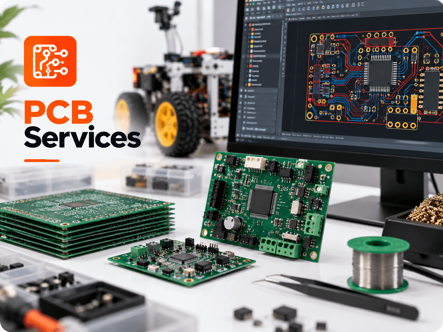
When engineering a printed circuit board, one of the key design decisions is component package selection: Surface Mount Technology (SMT) or Through-Hole Technology (THT). Today, over 85% of electronic components are designed for SMT assembly, but THT components remain irreplaceable for high-vibration robotics, high-current power connectors, and rugged industrial machinery. Most industrial boards are 'mixed-technology,' leveraging the strengths of both methods.
Surface Mount Technology (SMT): High Density and Automation
SMT components mount directly onto copper pads on the surface of the PCB without requiring drilled through-holes. SMD resistors and capacitors are available in microscopic packages (e.g. 0805, 0603, 0402), enabling extreme component density. Because SMT parts have minimal lead lengths, parasitic inductance and capacitance are drastically reduced, making SMT essential for high-speed microcontrollers (STM32, ESP32) and RF communication.
Through-Hole Technology (THT): Mechanical Strength and High Power
THT components feature metal lead wires that pass through drilled, plated holes in the PCB and are soldered on the reverse side. The solder fills the entire barrel of the hole, creating an exceptionally strong mechanical bond. THT is preferred for:
- Connectors and Terminal Blocks: Screw terminals, XT60 battery connectors, and DC barrel jacks subjected to repeated mechanical insertion and pull forces.
- High-Current Power Components: Large power inductors, high-wattage wirewound resistors, and bulky relays handling 10A to 30A.
- Large Electrolytic Capacitors: Bulk filtering capacitors whose height and mass could shear off surface-mount solder pads during mechanical shock.
| Parameter | Surface Mount Technology (SMT) | Through-Hole Technology (THT) |
|---|---|---|
| Component Placement | Top and/or Bottom surface pads | Leads inserted through drilled holes |
| Assembly Method | Automated pick-and-place & stencil reflow | Manual insertion & wave / hand soldering |
| Component Density | Extremely high; components on both sides | Lower; leads consume routing space on all layers |
| High-Frequency Performance | Superior (minimal parasitic inductance) | Moderate (longer leads increase parasitic inductance) |
| Mechanical Retention | Moderate; reliant on surface pad adhesion | Extremely strong; locked inside plated barrel |
| Board Cost Impact | Lower per-joint cost at volume | Higher drill count adds to bare fabrication cost |
Get SMT & THT Mixed Assembly for Your Hardware →
Go Now